Hidden Hydraulics at the Dam
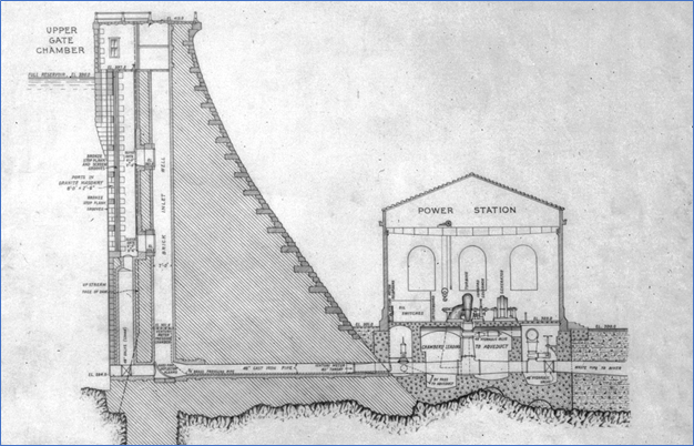
Upper Gate Chamber
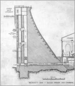
The path of the water from the reservoir into and through the intake structure (dam).
Lower Gate Chamber
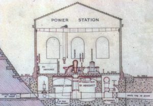
The path of the water through the powerhouse – aqueduct, turbines, waste conduits.
Pool & Fountain
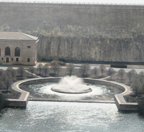
The path of the water from the powerhouse, through the pool and fountain, to the millpond.
Channel Velocity Control
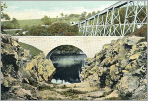
The Waste Channel (Spillway) discharges excess water, at high speed, into the millpond. How to slow it down??
Those engineers…they are all gone today, and a goodly portion of their records too. Their work remains in testament to their genius. It is for us to unravel the mysteries of how they did it.
In this series the work of the hydraulic engineers will be explored. The measures it took to safely handle the vast amounts of water will be reverse engineered, models made and presented.
Their main directives included:
Impound the entire flow of a regularly flowing river in a vast lake, up to a hundred feet deep, behind a strongly built dam.
Extract a fixed amount of that flow, direct it elsewhere and release the remainder downstream, passing it through a hydroelectric plant along the way.
Though the numbers can be a bit large to imagine, the concepts are really quite simple (i.e. higher pressures? stronger pipes!)
First in the series is a study of erosive power of the waste channel (spillway) and the measures taken to control it. Articles in development for future release include: the pool and fountain, piping inside the powerhouse, piping inside the dam, a close look at the waste weir etc.
There were hydraulic problems with the stopping of the river during construction, constructing temporary bypasses and effecting switchovers, and the continuous provision of water to users downstream.
Later this year, hydraulic engineering associated with the North Dike will be presented.
And remember, they accomplished it all with just horse, steam…and their heads.
Thanks,
Paul
___________________________________________________________________________